fighting procrastination fifteen minutes at a time

Category: Modelling (Page 2 of 3)

Switch build 01

Work on the first switch for Son of Test Track has started and it’s going to be a 150mm Radius with a 1:7 frog and 9mm track gauge. Why 1:7? It’s mainly because I have the frog nose and crossing jigs in that size. I use to have the whole set but over the years I have lent or misplaced the rest so these are the ones I have to hand at this time.

The process starts with a flat surface, in my case I’m using a lump of 1″ MDF that was a door off the bedroom furniture that came out when I first moved in. The template is spray mounted down to the flat surface and then a quick squirt over the top face to allow the copper clad sleepers from 2FS association to be applied to the template. Using some tweezers to get them to match up as best as possible to match up with the Center line. Now I’m starting to lay the stock rail but before I do I need to file out the pocket for the point blade and here endeth the fifteen minutes.

Until next time..

Rail height comparisons

fullsizeoutput_73fIn planning the track for the diorama I needed to find out what the height differentials were between the types  I am looking at using. In order for the scenic section to look somewhat realistic I decided on using some Peco Code 55 FS Concrete Sleepered track and then was contemplating a mixture of 2mm Association track in two formats, the Easitrac moulded plastic sleepering for the straight sections of the yard and then just plain old PCB and coiled code 40 rail soldered construction as used in the test track. I was asked by a friend why didn’t I just use the Peco? My reply was that I had all of the stuff there to build after years of stock piling and it’s so much cheaper. Have you seen the price of curved Streamline switches? But the payoff to using one type is you don’t hat to do any elevation on the road bed.

Now how did I go about measuring the gap? With no depth gauge or other suitable instrument I opted for a rather rough and ready feeler gauge alternative using some styrene sheet with combinations of .10/.20/.30 thousand mm to increment the height until I got a match but rubbing finger over the joint. Yes I know its not scientific or an accurate measurement but for my purposes it is good enough. So with this method in place I ascertained that the PCB to Peco needs a .40thou lift and the PCB to Easitrack is just .10thou of a millimetre. This then raises the question of whether the Easitrack is worth it and I am going to ditch it in favour of just straight interval soldered track like the test track though I may actually measure out the gaps and not freestyle it like I did previously.

Lastly the question is what to do with underlay on the scenic section. I have two types of it one with a rubber backing and a standard old fashioned cork I need to get measurements for these to see how much adjustment the different tracks will need to accommodate in order to provide quiet running and a smooth transition between the two track types.

fullsizeoutput_73d

Until next time

Test track #5

My posts are like buses at the moment, nothing for ages and then loads of them. Almost there and the circle is complete. I cheated and decided not to bus wire it as I thought it was overkill and just wanted to get the track running so as to get all the Z locos tested and ready to sell off. I’m still a little sentimental and nostalgic about the Swiss stuff but really want to concentrate on being able to purchase the new and pending Kato stock for my layout that I shall be building. But in building this dual gauge it does give me the seed of and idea for a true metre gauge/standard gauge layout someday in the future.

and finally just a glimpse at a full circumnavigation of said circle via the wonders of a 9v battery. Can I hear distant rumbles of thunder?

The very last thing to do is find a suitable rheostat switch to place in one corner.

Until next time..

All change..

It’s been a year since arriving at my current spot and now is the time to finally sort out my space. It’s the first time I have had the time and a space to be able to mould to my plans and so I have drawn up some ideas to help me decide what goes where. Now normally I’m guessing that most people have a reasonable amount of room to set up their model railway but in my case I have about 7 feet along a wall for layout and about the same for a bench, so some might think rather compact. With a bed the usable space becomes even more restrictive but then the challenge of how one goes about deciding the optimal use case is part of the fun for me.

First of all everything needs to come out and the room prepped for a coat of paint it’s been a bit of a drawn out process picking the colour as I wanted something darker not only to reduce light levels in the room but to also make a bit of a backdrop for taking photos and maybe some video in the future. As it is a north facing room light levels are lower but this works to my favour in that going for the “low key” effect a darker hue reduces the reflections. I know this is not necessarily railway modelling related but I definitely subscribe to a holistic approach and taking into account things like room environment is maybe something that is not given much though in the genesis of a railway room, it is as much about a bit of theatre as just a room to run a railway. Also I will probably only get one chance to setup as I want as the disruption of reinventing it would be too costly and time consuming.

Much of the room furniture needs to be configured to the need and as such I’m unlikely going to roll up to Ikea and return with a flat-packed solution. Due to the limited space I have measured up the workbench and desk to allow for a comfortable work height and depth and as can be seen from plan the idea of a fold up extension is to give me a good depth when modelling but can be folded away to not interfere with layout operation when I am playing trains! The idea of having to get out and put away may be onerous to some but for me it will be a help in that my natural tendencies to clutter and chaos will be curbed.

So now that I have the plan in place and have mocked up with CAD (and that’s cardboard aided modelling) I need to get on with the doing. Over the next week I’ll be making a start and will post on the progress.

Till next time

Test track build #4

The circle is now complete with both rails in place and glued down using just simple PVA glue with bluetack to hold the ends in place. I was surprised at how quickly it cured as I thought I was in for a lengthy wait before I could get on with the next section. I didn’t mark out the circle fully and completed the curves by site with one corner flattened out a bit but I wasn’t bothered about the accuracy with this only being a test track. One mistake I made was forgetting to wash off the inner rails flux in the excitement of moment, but I’ll remedy that with a soft wire brush and a damp cloth. I probably don’t need to do it but I will go round with a file and ease out any bumps though there are very few luckily. I amaze myself that it turned out so we after such a long absence of any kind of modelling. However if a jobs worth doing etc…

The next task is to drill holes in the board for feeder wires, hot glue these wires, and then terminate at a switch that can select between analogue or DCC control. I need to get this switch and a bunch of electrical connectors so I guess that means a trip to the model shop, what hardship!

Lastly a shot of three different scales on one piece of track. The Z stuff will soon disappear and who knows what might happen to the 009 loco. I also need to look into some better lighting for taking pictures and for seeing the workbench. I also find myself wanting one of the those bench mounted magnifying glasses or maybe just a new set of normal ones from Poundland. In fact there

Until next time..

Test track build #3

With having a couple of days off with other stuff going on today saw the completion of the four track panels bar a bit of fettling to get the rails to match up at the joins and the inner 6.5mm track fixing down I made a start on that too. I had considered using some road bed but felt it was a waste of time as this is only going to be used occasionally.

First rail laid down for Z tester. I didn’t bother with gauges and elected to use a cheap set of digital calipers to measure the gap holding rail in place by the age old method of fingers remembering to remove them just before it got to burning point. Tomorrow I’ll have all inner rails added and plan to glue down the track.

Till next time..

Test track build #2

Ok it took me slightly longer than 15 mins but keeping the momentum going. I have moved on from the first iteration and now building the ‘proper’ track in sections to make it manageable and also allow for some expansion. I’m building it this way as I found that from the previous straight piece it was easier to build the outer rails and then cut the isolation gap before attaching the inner rail for Z track.

Once I was happy with the alignment, well almost happy as it’s a little bit of a squeeze to get it to align I went and washed off with washing up liquid and an old toothbrush to get rid of any flux residue. Just need to make the last two panels of track before I can glue down and electrify.

Ironing out the rails

Arrgghhh, I started out last night writing this post almost getting to end when virtually all my hard thought prose were wiped off the face of the planet. When will I ever learn as this is not the first time I have been stung this way and thinking that writing the post in the WordPress app on my mobile device is a good idea. So from now on these posts will be hand crafted away from the web and then pasted in at the last moment. In this day and age I’m surprised that this still can happen and that web coders can’t have a back button on the WordPress app but that’s going way off topic.

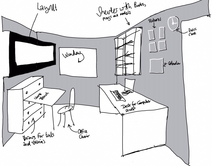
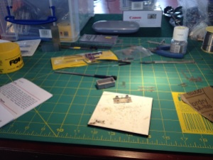
Ok, so finally something to show for effort and not just a blathering post about thoughts and plans, and what magazines I have been buying. As the observant of you will notice yes this is a bit of dual gauge track, but don’t look too closely at the soldering! It’s been some time since I last picked up the iron in anger and had to go through all the faff of digging out all the required bits and pieces such as solder and flux etc and then remember what temps I needed to set it at. That being said I have finally managed to light a bonfire under the mojo and get cracking with project 1 here at 15minutemodeller headquarters. Also in this pic is the baseboard knocked up to start this project off. For once no lengthy planning sessions were carried out in order to ascertain the optimum design, no 3D mockups to waste some more time creating cutting lists that would have made the builders of the Cutty Sark blush. No this was literally two lumps of batten chopped up and a chunk of ply grabbed from the wood pile and screwed and glued together in a blink of an eye. Unheard of? Yes! It’s certainly not beautiful but certainly functional if just a bit on the heavy side but then again I wasn’t going for experimental lightweight forms.

Now the reason for this test track is two fold; firstly to act as a 9 millimetre-ish and I say this as I plan to be able to use it for both my Kato stuff and also for some future 2mmFS plans as they can share the same gauge with no problems it’s only when switches are introduced that it becomes a bit sketchy. Yes I Know I said I was forsaking all other distractions but the reality is that I know I am never going to be able to limit myself to just one thing and also my plans for 15minutemodeller have changed to allow for my inveterate rubber gauge tendencies and hopefully more will be revealed over time.

Then the reason for the second and narrower gauge is to accommodate the testing my collection of both American and Swiss Z scale that I have now finally decided to liquidate. In order to put the locos on a well know auction site I need to check to see if there running ok as it is an not insignificant amount of time since I last took them out of there boxes and ran them. Plonking and extra rail on the test track to facilitate this is no real extra effort and who knows whether it might be of use in the future. Just after building the board rummaging through the boxes I uncovered the rolling road I brought many moons ago, in fact not just one set but two, jeez that was a time of way too much money and little sense although in this case it paid off as going forward I will be using these to run locos in, but then there is something relaxing about watching a train trundling around a track. We’ll see how long the test track survives after the locos it’s built for have left the building.

Just as a side note one can build hand laidback with nothing but a set of callipers either manual of digital and you don’t need fancy brass gauges in order to build something operational, points/switches may be a little more challenging but not impossible. So to get the very rusty soldering muscles going I built a very small section of straight dual gauge from a recycled point I made for another project years ago, to test out the workflow needed to build the full circle and I’m glad I did it as it point out some failings in my thinking about how I was going to put things together.

It’s great to smell the aroma of 60/40 again and now that I have the platform to build on I just need to get some metal down.

Until next time..

Measure twice cut once

If only I had headed those words and not gone to B&Q without my backofanenvelope calculations which left me with ply cut short. However after a bit of head scratching and ponder and some tea drinking I realise that I could add on a section at the end. Due to the lightweightedness of the baseboard it shouldn’t be too much of a problem and with extra bracing for attaching to the main board everything should be rock solid!

However in the measuring fiasco it means that I will need to get some more ply for the top and so a trip out to the timber merchants on Monday for another sheet of 8×4 6mm ply. This does mean I have quite a lot left over! Do not be distracted, do not be distracted… repeat.

IMG_2308

Back on the Wagon

After a rather too long a hiatus in modelling terms due to life getting in the way I have managed to get back to the workspace. Yesterday I attended the NEAG meet that was primarily for getting people building and most of us built a 2mmFS Mineral Wagon kit and had the challenge to complete it by the end of the day. I didn’t get off to a good start by forgetting my soldering iron (I have at least 5 with the temp controlled one I was going to take got out ready the night before, and a craft knife) Thankfully one was provided for me and I cadged off my fellow AG member for the knife. It also realised/remembered that there are all sorts of little jigs and things like Blutac and hair clips. I have also been thinking about toolbox build and adapting it to my needs. I therefore haven’t moved ahead with this yet but I have make contact with local timber merchants who will supply and cut good quality Birch Ply along with carcassing timber for another project.

Unfortunately I didn’t manage to get that far but I certainly managed to get a good way on with it. The boost it provided has got be back to getting on with my modelling and certainly will keep momentum going as I got another kit to bring home with me to start as soon as I have finished the first one. In fact I have a rake of about 15-20 to build of these so once I have completed one to my satisfaction I will start batch processing.

This leads me on to what to run these on. Well I am going to try to build a foam board micro, a kind of inglenook keeping it simple!! but building some things that can be transferred to the ‘big’ layout. But less talking more doing! 🙂

Wagon kit building

Wagon kit building starts


Before lunch

Before lunch


Somewhat nearly finished

End of the day


« Older posts Newer posts »